Self-Tapping Helical Inserts
Self-Tapping Helical Inserts
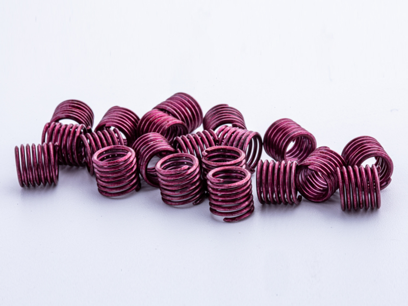
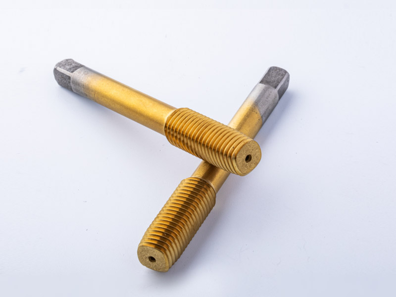
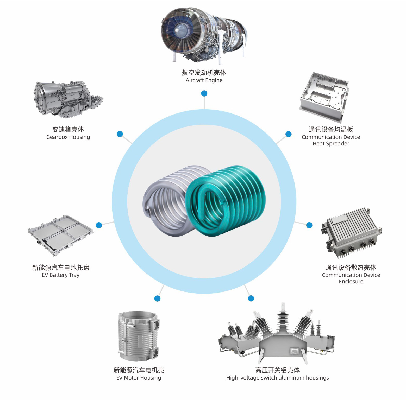
Self-tapping thread inserts (also known as self-tapping sleeves) are fasteners with internal and external threads, featuring cutting holes or cutting slots. They do not require pre-tapping; instead, they are driven directly into the base material to form their own internal threads. They can also restore damaged or stripped threads while maintaining the original thread size.Self-tapping inserts are suitable for light alloys (aluminum, magnesium, zinc, and their alloys), cast iron, brass/bronze, thermoset plastics, laminates, and wood. They are widely used in automotive engines, transmission components, and other parts such as mirrors, heat sinks, and shock absorbers; in factory equipment such as flange joints, construction machinery, and fuel systems; in household appliances and office equipment; as well as in capacitors, high-current devices, RF and telecommunication systems, and dental equipment. In the military field, they are mainly used in tanks, fighter jets, naval vessels, and other equipment.Advantages of Self-Tapping Inserts
Self-tapping inserts can cut their own threads, eliminating the need to pre-tap the base material, thus reducing production costs.
They have a large contact area with the assembled part, providing high tensile strength, allowing the use of lower-strength materials in design.
They can restore worn or stripped threads in the base material, allowing the continued use of the same screws.
They offer excellent vibration resistance, preventing loosening.
They fit tightly with the base material, providing good airtightness even when the base contains air bubbles.
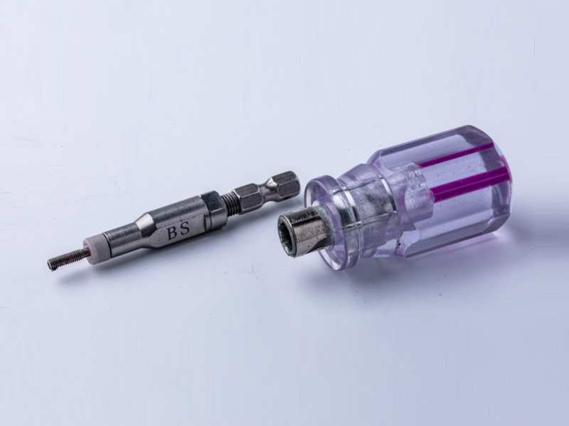
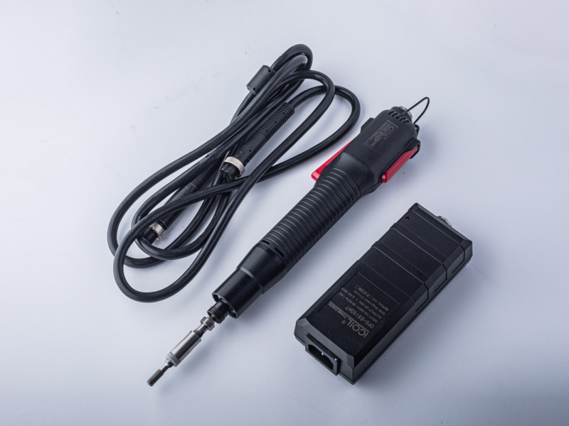
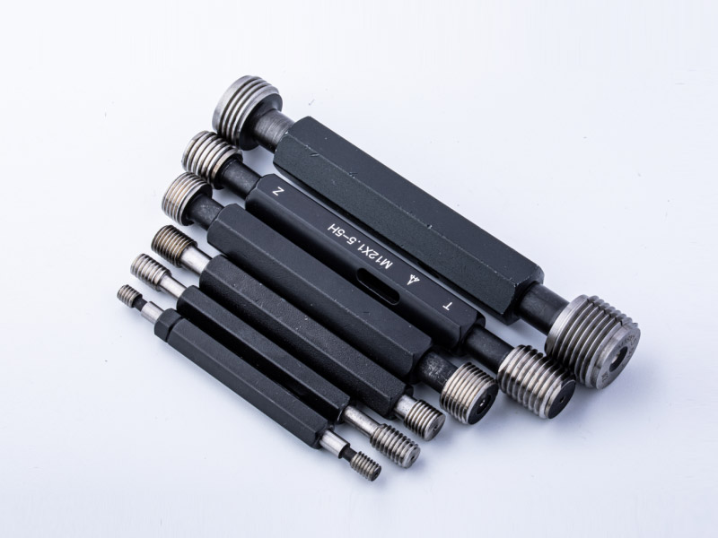
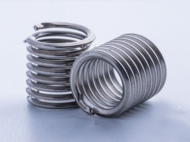
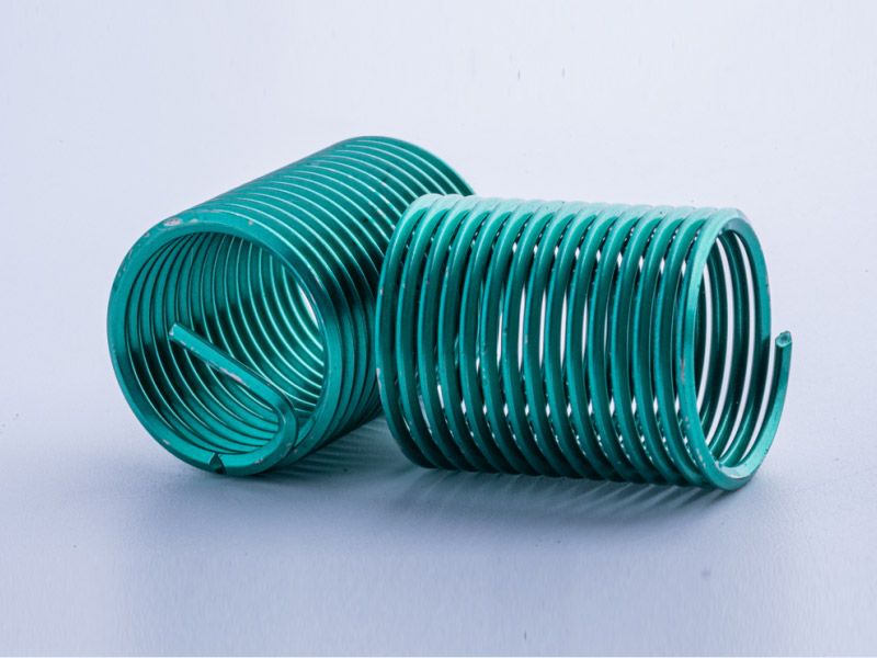
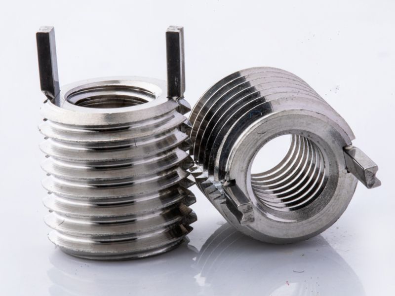
Self-tapping inserts are easy and quick to install, requiring only one assembly tool, with low cost and virtually no defect rate.Types of Self-Tapping Inserts 302 / 302H Type The 302 series is the most widely used among all self-tapping inserts. Its two slots serve as cutting edges and provide a slight inward locking effect. The 302H version adds a flange to the 302 type, significantly increasing pull-out strength and torque resistance.307 / 308 TypeThe 307 and 308 series are designed for difficult-to-cut materials. They feature a thicker wall and a shallower yet sharper external thread, and use three holes as cutting edges. The 308 is a reinforced version of the 307, with the only difference being the insert length. The 307H / 308H versions include a flange.317 / 318 TypeThe 317/318 series is specially designed to provide increased torque capacity and vibration resistance, achieved by inserting a pin that conforms to DIN 1437 standards.Common Materials for Self-Tapping InsertsCarbon SteelSuitable for lower-strength base materials such as aluminum alloys, copper alloys, and plastics.Stainless Steel 303Suitable for higher-strength materials such as cast iron.Installation Method for Self-Tapping InsertsMethod 1:When the installation quantity is small, a simple installation method can be used. This method uses a bolt and nut of the corresponding size. As shown in the illustration, fix the self-tapping insert onto the corresponding bolt, then secure it with a nut of the same specification so that the three components form a single unit. Use a wrench to drive the insert into the pre-drilled hole, then remove the bolt after installation.Method 2:When the installation quantity is large, a dedicated insert installation tool can be used. The procedure is illustrated below. The rear end of the tool has a hex head, which can be connected to a manual tap wrench or to electric/pneumatic tools.Step 1Drill or form the hole according to the recommended and verified diameter. Screw the self-tapping insert onto the manual installation tool with the cutting slot or cutting hole facing downward. Ensure that the tool’s tip does not extend beyond the upper cutting point or the upper edge of the slot.。Step 2Drive the insert vertically into the hole. During the first 1–2 threads of engagement, check for misalignment. If any deviation occurs, remove and realign immediately. Do not reverse the installation tool during the tapping process.Step 3When the insert reaches the intended depth (the top of the insert should sit approximately 0.2 mm below the work surface), hold the lower hex nut with a hex wrench and rotate counterclockwise to remove the installation tool.Installation PrecautionsFor different base materials, refer to the recommended drill size to perform the pre-drilled hole. When the material has higher hardness, slightly enlarge the hole diameter within the recommended drilling range.Position the slotted end or the three-hole end downward, secure the self-tapping insert onto the installation tool, and align it vertically with the workpiece. During initial insertion (1P–2P), ensure precise alignment with the pre-drilled hole; the tool must never be tilted. If misalignment occurs, do not reverse the tool—remove and realign before proceeding. After the insert has entered 1/3–1/2 of its length, reinstallation is no longer possible. Also, do not reverse the tool during installation, as this may cause insert failure.Once the insert reaches the designated depth, hold the hex section of the tool with a locking plate and reverse the wrench to detach the tool from the workpiece.